Right click to see larger picture
Then I learned of an upcoming DX listening contest for radios that use only one active device. I began optimizing the basic Bazian circuit to become my DX entry in the contest. The biggest unknown was the RF transformer. There were no specifications for it until Robert Bazian graciously answered my inquiry. His radio was not intended for DX, so I experimented with many, many configurations and finally decided that a lot of them produced the same sensitivity. However, each came with various side effects such as hysteresis (backlash) and painfully annoying motorboating and screeching. For the contest, I settled on one of the first RF transformers I wound, and my contest radio performed superbly.
Testing my contest
radio, I stumbled upon the elegant notion of using the RF transformer
to introduce positive feedback, transforming the already powerful reflex
circuit into a true regenerative reflex radio. The noisy side effects
manifested themselves only when I had the regeneration cranked up too high.
Under time pressure, I decided to accept them as necessary consequences
of such a simple radio. I found that if I was careful with my fine
motor skills, I could avoid most of the ear splitting blasts.

Right click to see larger picture
I was so smitten by this little jewel, that after the contest, I began optimizing it further. I tried more RF transformers and realized that they all interacted inductively with the tank coil, no matter how I tried to isolate them. It was difficult to make progress because there were too many variables. I concluded that the regeneration source should be separated out from the RF transformer. The resulting schematic below differs from the contest radio in that it employs a tickler coil. It also does away with the external antenna.
With a separate tickler the RF transformer should be shielded. Previously I'd met Charles Wenzel and he'd generously given me a couple of the ISDN tranformers like he uses in his version of Robert's radio. I settled on using one of those. It's the black rectangular object (with white lettering) near the middle of the circuit board in the picture to the left, seen at the left end of the long ferrite rod.

Right click to see larger picture
Tapped tickler coil provides both positive and negative feedback for wide range RF control; I've never seen this before and I'm very happy with how well it works
Contrawound tuning coil provides dual range tuning for high Q and very fine control (silver switch next to tuning coil is range switch)
High Q variable capacitor was intended to optimize performance; in fact, the radio can perform as well with an inexpensive poly capacitor
70 volt line transformer provides optimum matching for headphones or speaker
Dial string tuning with 13:1 slow motion ratio aids in razor sharp tuning
Heavy flywheel provides for buttery smooth action, a pleasure to operate
Slide rule dial with 3/32" per 10 kHz at the upper end of the AM dial makes locating stations extra satisfying
Eight pin IC socket permits easy substitution of transistors and diodes
Previous version (not shown) used dual back-to-back diodes to smooth regeneration and control howling; not necessary with tapped tickler version
Inexpensive shaft couplers made from hardware store nylon bushings and set screws
Optional external antenna coupling using contrawound air core coil

Right click to see larger picture
No external antenna is necessary; adding one increases performance impressively
Smooth regeneration all the way from negative feedback to raucous oscillation, no hysteresis or backlash
Regeneration control is so fine that synchronous homodyne reception is possible
Local reception drives speaker to room filling volume using no extra amplification-click here to listen (This recording was made with a stereo microphone placed two feet from the radio speaker)
Audio output is strong enough to use ordinary stereo headphones on the weakest signals
Sensitivity sometimes exceeds that of commercial DX radios
10 kHz selectivity with adjacent loud locals
External antenna coupled with contrawound air core coil increases chances of beating commercial radios
Click on mp3 recordings below for further demonstrations

This recording was taken directly from the radio's headphone output into the recorder line-in

This recording was taken directly from the radio's headphone output

This recording was made with a stereo microphone placed two feet from the radio speaker
| Ben Tongue graciously accepted my
request for his evaluation of this circuit. I sent him my prototype.
He responded with the following coments: Hi Tom, The performance of the Macrodyne is remarkable. I'm truly amazed at the undistorted, loud earphone volume it supplies from many stations, with no external antenna. The nearest 50 kW stations are about 10 miles from my home. On Sunday, Sept. 23rd at 4:30 PM, I decided to see how many stations, at a reasonably loud earphone volume, I could Log. Their frequencies were: 570, 620, 620, 660, 710, 770, 820, 880, 930, 1010, 1050, 1130, 1190, 1250, 1280, 1380, 1430,1530, 1560, 1600 and 1660. However, 570, 620, 1530 and 1660 were weak, but fully understandable. I wonder if a different diode bias current would help with weak stations. Selectivity was great. I tried to find specs on the Internet for the little PCA EP6091 8346 RF transformer. It seems to me that the Company that made it is now out of business. If you have the specs, I’d like to review them. Thanks for giving me a chance to experience the performance of the radio. I plan to ship it back to you, from Blonder tongue, in its original box, on Tuesday, Sept. 25. On the same day I'll send the ferrite cores, battery and headphones in a separate package. Best regards, Ben |
| PRIOR ART I wondered how many years back reflex radios had been used. They were pretty popular until the superheterodyne took over. The following page of a book from the thirties shows a circuit to the right that's strikingly similar to the Macrohenrydyne. On a related note, below is the schematic of the basic homodyne. Click here to to read the fascinating homodyne history. |


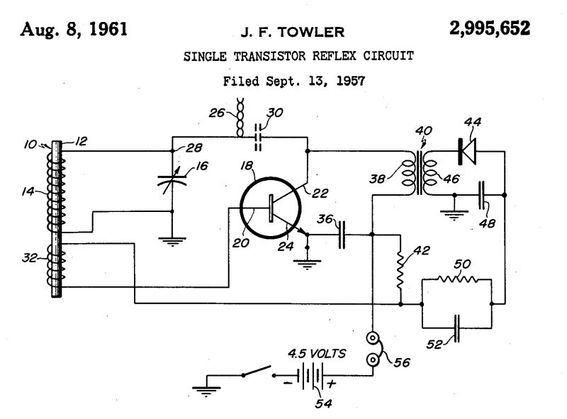
Shortly after I.D.E.A. Corp introduced the first transistor radio to the masses, the Regency TR-1, one of their following products was a single transistor reflex radio, invented by J. F. Towler. The following image is from his patent.